In this post I look at how to drive the PiFace Digital 2 card with CODESYS. The post is aimed at CODESYS beginners.
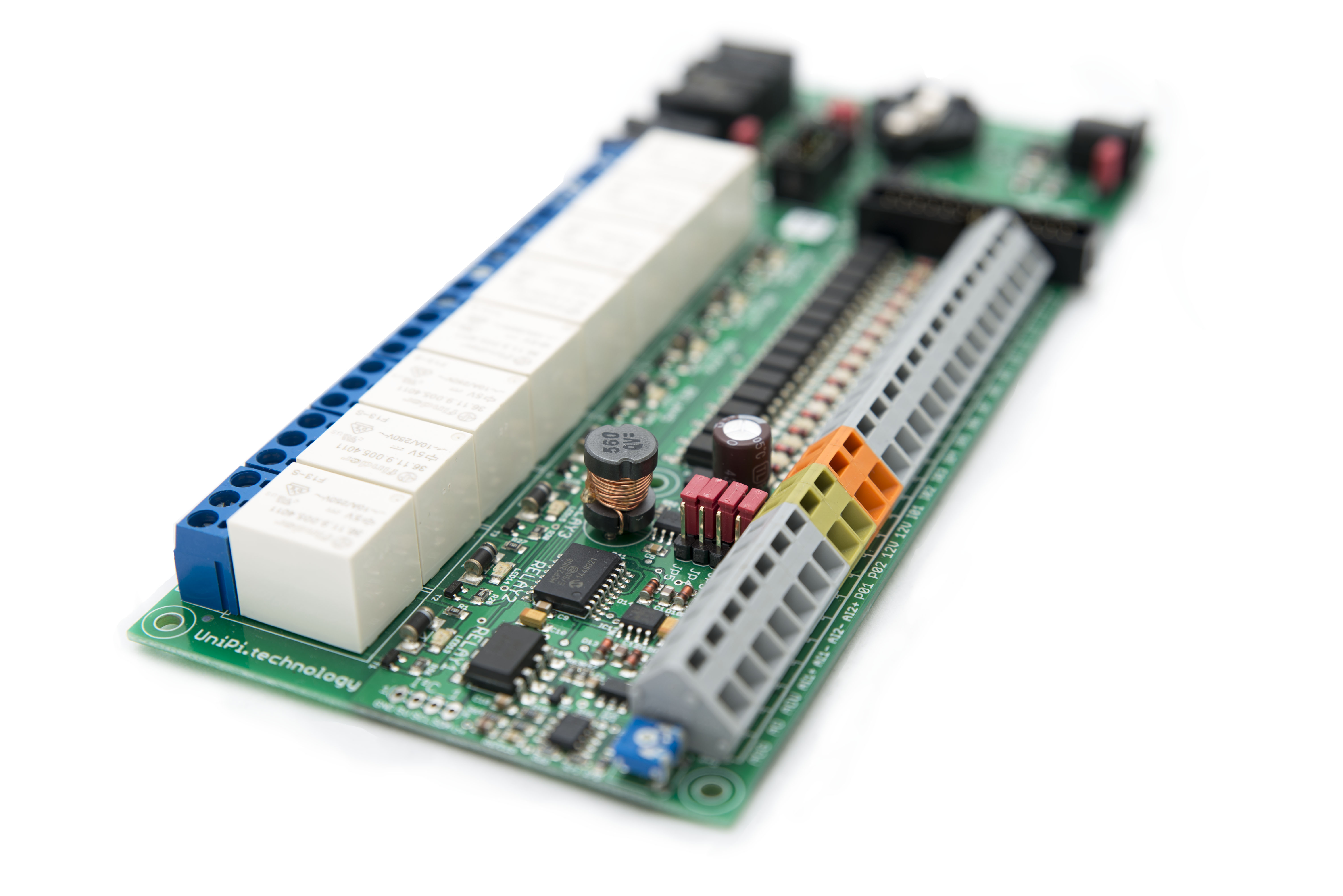
The PiFace Digital 2 is provides 8 open collector digital outputs with LED indicators (two of which also drive changeover relays) and 8 digital inputs, four of the inputs are in parallel with on board switches. Fundamentally the guts of the board is a MCP23S17 16 bit I/O expander, so we will need to configure appropriate SPI devices in CODESYS.
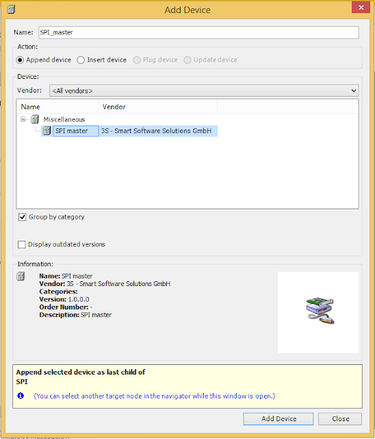
First create a new project in CODESYS with ST as the selected language. The PiFace Digital 2 module is based around an SPI latch, so we need to configure the required SPI devices. In the Devices pane right click on the SPI device and select Add Device…
This brings up the Add Device dialog, select SPI master, and click the Add Device button.
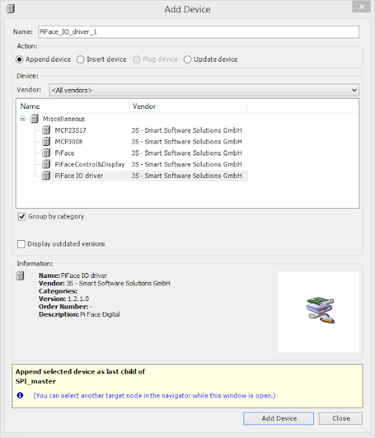
Then in the Devices pane select the newly added SPI_master device (do this without closing the Add Device dialog). The Add Device dialog will update to show SPI slave devices that can be added, select the device named PiFace IO driver, click the Add Device button and then close the dialog.
It is possible to connect up to four of these boards to a single Raspberry Pi, to identify individual boards the address is set with a pair of links. If the board is in its default configuration then we should have nothing to do, but we should check, so inspect where JP1 and JP2 are connected, the table below shows what address this represents.
|
|
JP1 1-2
|
JP1 2-3
|
|
JP2 1-2
|
0
|
1
|
|
JP2 2-3
|
2
|
3
|
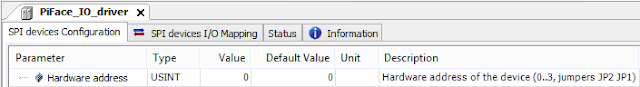
Open the PiFace_IO_driver device in CODESYS and verify that the Hardware Address parameter matches the value from the table.
We are now all set to test that our PiFace Digital board is working in CODESYS. The easiest way to do this is to create a simple program to copy the Inputs to the Outputs.
The program just copies one VAR of type BYTE to another, to use the actual inputs and outputs change we need to map these VARs onto the IO. To do this use the mapping tab (SPI devices I/O mapping) in the PiFace_IO_driver pane. Double click in the Variable column, and either type in the fully qualified variable name, or click on the elipsis and use the Input Assistant to find the variable.
If you now go online and download this application to your Raspberry PI you should be able to change the state of the outputs by triggering the inputs on the PiFace Digital. You can test the least significant four bits using the switches on the board.